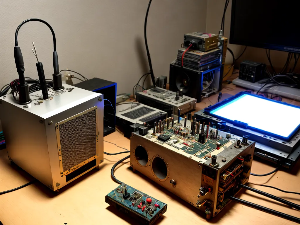
Building an Electronic Theremin Using Scrap Parts
As an electronics hobbyist, I am always looking for fun DIY projects to build using spare parts I have lying around. Recently, I decided to try making my own electronic theremin using scrap materials. For those unfamiliar, a theremin is an electronic musical instrument that you play without touching. It was one of the first electronic instruments ever invented.
Gathering Materials
The most important components I needed for my DIY theremin were:
-
Two oscillators - To generate the audio tones. I used two old 555 timer IC chips since they can easily produce audio frequencies.
-
Antennas - These detect the hand position of the player to control the pitch and volume. I fashioned small antennas out of stiff wire.
-
Amplifier and speaker - To amplify the weak oscillator signals to an audible level. I dug up an old mini audio amplifier and small speaker from a broken music player.
-
Power supply - To power the oscillators and amplifier. I used a 9V battery holder with fresh batteries.
-
Wires, resistors, capacitors, potentiometers - Various miscellaneous passive components I had in my parts bins.
-
Project enclosure - To mount all the components in. I used a plastic food container.
The simplicity of the theremin circuit meant I could build one using just basic components and materials I already had on hand.
Constructing the Pitch Control Oscillator
The theremin has two separate oscillators - one to control the pitch, and another to control the volume.
I started with building the pitch oscillator using a 555 timer chip. This generates an audio tone that changes frequency based on the position of the player's hand near the pitch antenna.
To make the oscillator's output frequency adjustable, I used a potentiometer connected to pins 6 and 7 of the 555 chip. This acts as a variable resistor to alter the chip's internal RC timing network. Turning the potentiometer knob raises or lowers the frequency.
I also added a fixed capacitor between pins 6 and 7 to help set the center frequency and tuning range. The oscillator's output pin 3 was connected to the amplifier/speaker through a coupling capacitor to block the DC voltage.
Constructing the Volume Control Oscillator
The volume oscillator circuit is similar, using another 555 timer chip. But instead of the frequency changing, the output amplitude varies based on the hand position near the volume antenna.
I adjusted the resistor and capacitor values connected to pins 6 and 7 so this oscillator operates at a fixed high frequency, around 15 kHz. The output amplitude decreases as capacitance on the volume antenna increases when the player's hand gets near.
To convert the oscillator's amplitude changes into volume changes, I used a diode envelope detector circuit connected to pin 3. This outputs a DC voltage proportional to the AC signal amplitude. This DC voltage is then fed through a resistor into the amplifier's volume control.
Antennas and Enclosure
For the pitch antenna, I used a long stiff wire about 2 feet long. For the volume antenna, I made a loop antenna using stiff wire. I mounted the antennas to my plastic enclosure, spacing them a couple inches apart.
After wiring up the oscillators, power supply, amplifier, and other components inside the enclosure, I attached an on/off switch and the pots to control pitch and volume from the outside.
Finally, I hot glued the small speaker to the side and drilled ventilation holes. Some creative labeling with paint pens finished off my homemade DIY theremin!
Playing My Homemade Theremin
After powering on my creation, I was excited to start playing some eerie theremin music!
Moving my hands near the antennas immediately produced swooping sci-fi sounds. Getting a feel for the hand motions to control the pitches and volumes took practice. But soon I was able to perform basic melodies on my DIY instrument.
While tricky to play precisely, the result was quite satisfying. The flexibility to design a custom theremin using scraps made this an enjoyable electronics project. Experimenting with component values and antenna designs will help refine the performance for future iterations. All in all, this was a fun way to recycle parts into a unique musical device!