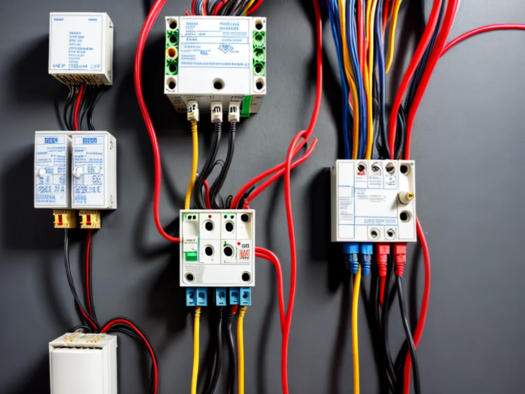
How to Wire a Three-Phase Delta System
Introduction
Wiring a three-phase delta system can seem daunting at first, but with some basic knowledge of electrical theory and standard wiring practices, it can be done safely and efficiently. In this guide, I will walk through the step-by-step process of wiring a three-phase delta system from start to finish.
Understanding Three-Phase Power
Before wiring a three-phase system, it's important to understand what three-phase power is and why it is used.
Three-phase power uses three different voltage sine waves that are out of phase by 120 degrees. This creates a more consistent power output than single-phase power. Three-phase systems are commonly used for large equipment, industrial machinery, and commercial buildings because of their ability to efficiently transmit large amounts of power.
Some key advantages of three-phase power:
- More efficient transmission over long distances
- Ability to power larger equipment and machinery
- More consistent power output and less voltage fluctuation
The three phases are typically labeled Line 1, Line 2, and Line 3. Each carries the same voltage but reaches its peak at different times.
Wiring a Delta Configuration
There are two main ways to configure a three-phase system: delta and wye.
In a delta configuration, the three voltage sources are connected end-to-end in a triangular shape. This gives you a voltage difference between each pair of phases, which can power loads.
Some key properties of a delta system:
- Phase-to-phase voltage is √3 times higher than phase-to-neutral
- Often used for motor loads and other inductive loads
- Does not require a neutral wire
Step-by-Step Wiring Process
With a basic understanding of three-phase and delta systems, we can now go through the wiring process step-by-step:
1. Install the Electrical Panel
The three-phase power will originate from the main electrical panel. A proper NEMA-rated enclosure should be installed to house the wiring and components. Use the appropriate size enclosure for the number of phases and loads being powered.
2. Run the Three-Phase Feeder Wires
From the electrical panel, run three sets of thick gauge feeder wires to the location where the three-phase loads will be powered. Common wire sizes are #6, #4 or #2 AWG for most applications. Each set of wires will correspond to one of the phases - Line 1, Line 2, and Line 3.
3. Install Disconnect Switches
Mount individual disconnect switches for each phase near the three-phase loads. This allows each phase to be manually disconnected for safety during maintenance. Use appropriate NEMA-rated switches/fuses for the voltage and load current.
4. Connect the Loads
At the three-phase load location, connect each load between two phases in a delta configuration. For example, connect Load 1 between phases A and B, Load 2 between B and C, and Load 3 between C and A. This evenly distributes the loads across the three phases.
5. Connect Grounding Electrodes
Connect the grounding electrode system to the delta-connected system. This provides a path to safely dissipate voltage surges, lightning strikes, and other electrical anomalies. Use proper ground rods, conductors, and connections as required by NEC code.
6. Check Voltages and Phasing
Before energizing the system, use a multimeter to check that the phase-to-phase voltages are correct. Also verify the phasing is proper using a phase rotation meter. The phase sequence should be A-B-C when reading clockwise.
7. Energize and Test
With all loads and meters disconnected, energize the three-phase feeder wires from the panel and test that the proper voltages are present on each phase. Reconnect meters/loads one phase at a time and check phase-to-phase voltages under load. If voltages are stable, the delta three-phase system is wired correctly.
Conclusion
Wiring a three-phase delta system requires attention to detail, adherence to electrical codes, and safe practices. But with the right knowledge and precautions, a properly functioning system can be achieved. The advantages of three-phase delta power can then be utilized for motors, machinery, and other applications. Just take it step-by-step and consult a qualified electrician if unsure during the process.