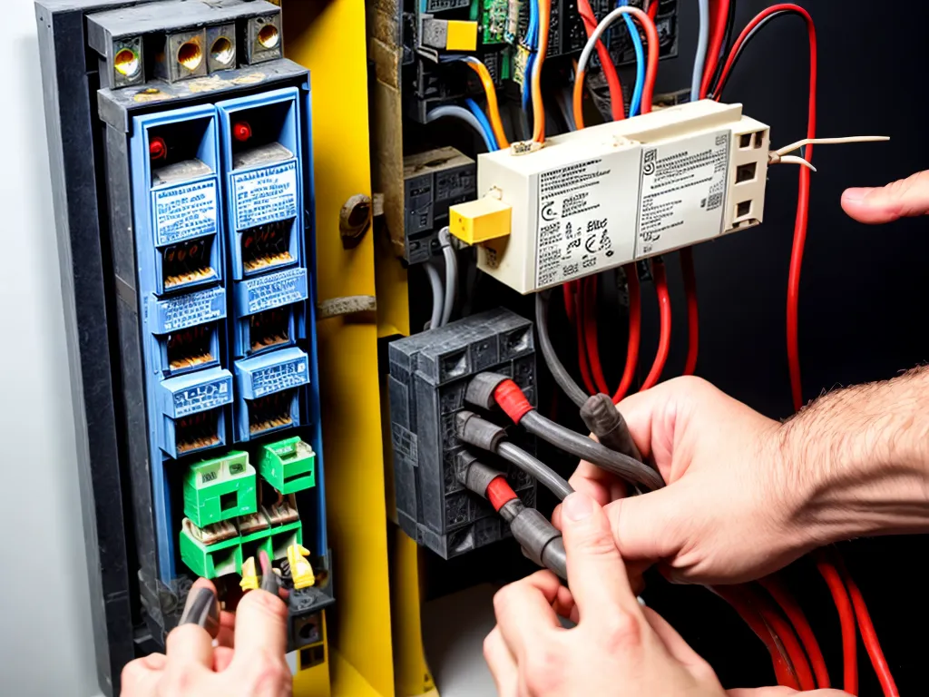
Transformers are essential components in electrical systems that are used to step voltages up or down. Three-phase transformers allow the power from a three-phase system to be transformed to meet different voltage requirements. Wiring a three-phase transformer properly is crucial for safe and effective operation. In this comprehensive guide, I will walk through the complete process of wiring a three-phase transformer.
Understanding Three-Phase Power Systems
Before wiring a three-phase transformer, it is important to understand how three-phase power systems work.
What is Three-Phase Power?
Three-phase power uses three different voltage waveforms that are 120 degrees out of phase with each other. This creates a more consistent power output compared to single-phase systems.
The three phases are typically labeled L1, L2, and L3. In a balanced three-phase system, the voltage on each phase is equal in magnitude and the phases are spaced equally.
Advantages of Three-Phase Power
Some key advantages of three-phase power include:
- More efficient transmission over long distances
- Ability to produce a rotating magnetic field, useful for motors
- Lower voltage fluctuations compared to single-phase
- Balanced loading on each phase
Three-Phase Transformer Function
A three-phase transformer is used to step voltages up or down while maintaining the three-phase power characteristics. The transformer has three sets of primary and secondary windings, one for each phase.
Proper wiring of the transformer ensures the phase relationships are preserved from the primary to secondary sides. This is critical for supplying three-phase power to downstream loads.
Wiring a Three-Phase Transformer
When wiring a three-phase transformer, follow these key steps:
1. De-energize the Transformer
Safety first! Before wiring the transformer, confirm the unit is de-energized and locked out according to electrical safety procedures. Attempting to wire a live transformer is extremely dangerous.
2. Select Appropriate Wire Size
Select wiring gauges that can safely handle the full-load current of the transformer. Refer to electrical code books for ampacity ratings based on your transformer KVA, voltage, and type of insulating material.
For example, a 45 KVA transformer with 600V primary may require #4 AWG copper wiring. go up a size or two for safety margin.
3. Connect Primary Side Wiring
The primary side connections are typically labeled H1, H2, H3 corresponding to L1, L2, L3. Bring in your three-phase supply to these points.
Match phase colors to maintain proper phase relationships. For example, connect black (L1) to H1, red (L2) to H2, and blue (L3) to H3.
4. Connect Secondary Side Wiring
The secondary side connections are labeled X1, X2, X3. Connect your three-phase load wires to these points.
Again, match phase colors to maintain phase rotation. Connect black to X1, red to X2, and blue to X3.
5. Ground the Transformer
Connect transformer ground lugs to your grounding electrode system. This provides an earth reference and fault protection.
Use properly sized grounding conductors per electrical code requirements.
6. Check Connections
Visually inspect all wiring connections to ensure they are tight and secure. Loose connections can lead to overheating and potential transformer failures.
It doesn't hurt to tug test each wire as an extra precaution.
7. Apply Power and Test
With all safety precautions in place, apply power to the primary side. Use a voltmeter to confirm the expected voltages on the secondary side.
Check phase rotation by testing phase-to-phase voltages. You should see the 120 degree phase shifts between L1-L2, L2-L3, and L1-L3.
If issues are found, de-energize and re-check all wiring before attempting to reapply power.
Special Wiring Considerations
Certain types of transformer connections call for specific wiring techniques:
Delta-Wye Transformers
For a delta-wye transformer, the delta winding becomes the primary. The line voltages are connected phase-to-phase. The wye winding is the secondary, with phase voltages from line to neutral.
Wye-Delta Transformers
A wye-delta transformer has the wye winding as the primary. The neutral point must be grounded. The delta winding is the secondary with phase-to-phase connections.
Single Phase Taps
Some three-phase transformers provide single-phase taps to obtain lower voltage single-phase outputs. These taps have to be wired as well during installation. Consult the manufacturer’s diagram.
Parallel Operation
For heavy loads, multiple transformers can be connected in parallel. Proper wiring helps share the load equally across all units.
Conclusion
Wiring a three-phase transformer requires carefully following the manufacturer's diagrams, matching phases, selecting proper wire sizing, grounding, and testing voltages/phase rotation before energizing. Taking the time to wire the transformer correctly will provide safe, reliable operation and long equipment life. Proper planning and precaution goes a long way for three-phase transformer installations.